
If you’re a property manager, general contractor, or IT director planning a DFW commercial build-out, the telecom room may be the most consequential space decision in the project. It’s also the one most likely to be treated as an afterthought. Getting the telecom room Dallas commercial buildings need requires understanding the hierarchy of spaces that structured cabling is built around. You need to know what each space must contain — and what happens when any of them are sized, located, or built incorrectly.
This article explains the MDF/IDF architecture that governs every multi-floor DFW commercial building. It covers what the governing standards require for each space, and which decisions must happen during design — not after drywall goes up.
What MDF and IDF Actually Mean
Structured cabling in a commercial building is organized around a hierarchy of distribution points. Every cable in the building ultimately connects back to one of these spaces.
The MDF — Your Building’s Network Core
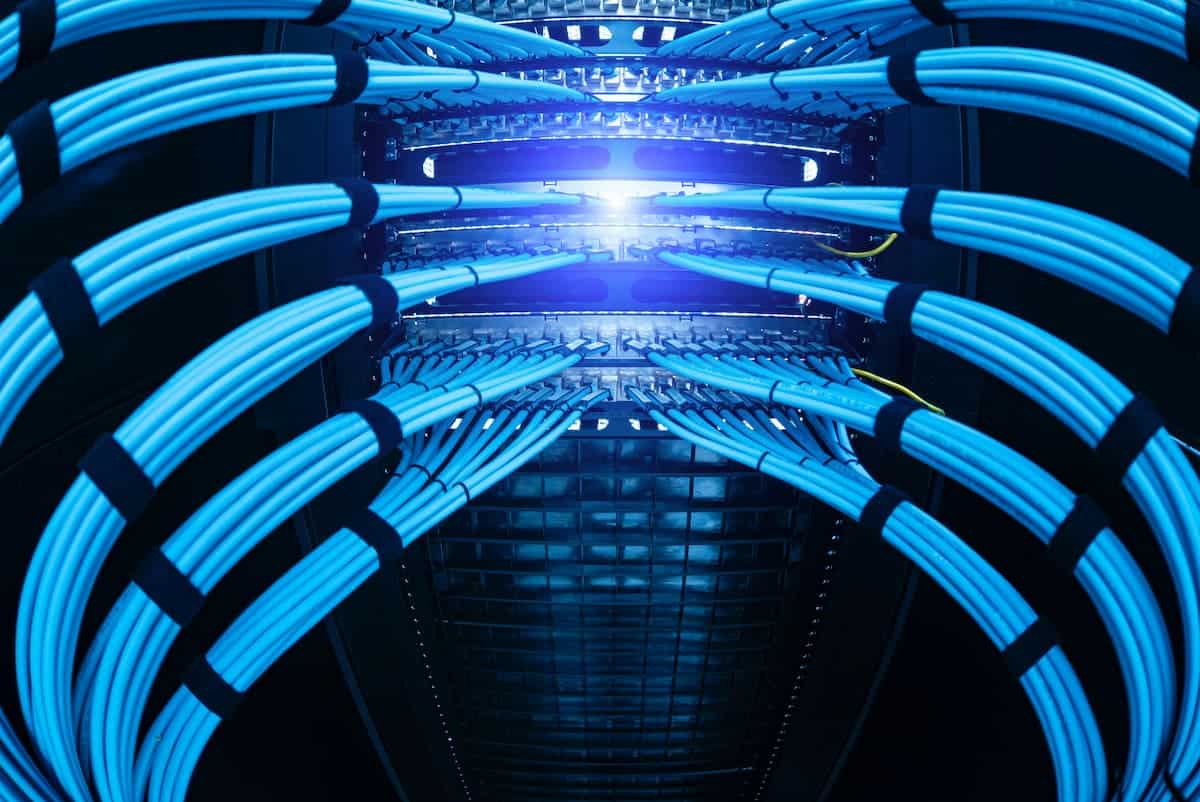
The MDF — Main Distribution Frame — is the primary hub of the building’s network infrastructure. The building’s internet service enters here. Core network switches live here. Fiber backbone cables from every floor terminate here. In a single-floor building, there’s typically one MDF. In a multi-floor DFW office building, the MDF usually sits on the ground floor or in the main equipment room.
IDFs — The Floor-Level Distribution Points
IDFs — Intermediate Distribution Frames — are the satellite closets that serve individual floors or zones. Each floor needs at least one IDF. The IDF houses the floor’s network switch, the patch panels where horizontal cable runs terminate, and the fiber backbone connection back to the MDF.
The 100-meter maximum channel length in the ANSI/TIA-568 standard for Cat6A horizontal runs is measured from the wall plate to the patch panel in the IDF. Every IDF must sit close enough to every workstation drop on its floor to stay within that limit.
The relationship is simple: the MDF is the network core, IDFs distribute to each floor, and horizontal cable runs connect individual devices to the nearest IDF.
Why Telecom Room Dallas Build-Outs So Often Get It Wrong
The most common telecom room Dallas build-out mistake isn’t technical — it’s spatial. Architects size telecom rooms without input from a cabling contractor or network engineer. The result is closets that can’t physically fit the racks, patch panels, and cable management the installation requires. There’s no room to grow.
Room Size Requirements
The ANSI/TIA-569 standard defines minimum room dimensions based on the floor area the room serves. A telecommunications room serving up to 1,000 square meters — about 10,800 square feet — needs a minimum space of 3 meters by 3.4 meters. Minimum ceiling height is 2.4 meters. These are minimums, not recommendations.
A telecom room built to minimum dimensions for its current tenant load has no room for the adds, moves, and changes that will happen over the building’s 15-to-20-year lifespan. Build bigger than the minimum. You will use the space.
IDF Placement Errors
The second most common mistake is location. An IDF at the far corner of a floor instead of a central location creates cable runs that exceed 90 meters before patch cords are added. That’s a spec violation. You can’t fix it without moving the closet or installing additional IDFs.
In DFW’s large-floor commercial buildings in Frisco, Las Colinas, and the Legacy corridor, floor plates of 20,000 square feet and above routinely need two IDFs per floor. One centrally placed IDF simply can’t reach every drop within 100 meters on a floor that size.
What Every Telecom Room Dallas Building Needs Inside
Whether it’s an MDF or an IDF, every telecommunications room needs the same core elements — sized and configured for its role.
Dedicated Space — No Shared Use
A telecom room should contain only telecommunications infrastructure. No water pipes, HVAC equipment, electrical panels, or storage. The TIA-569 standard is explicit on this point. Shared use introduces moisture risk, heat load, physical access conflicts, and maintenance disruptions. In older DFW buildings, telecom rooms that double as janitor closets or mechanical overflow spaces are a recurring problem — and a recurring cause of equipment failures.
Environmental Controls
Network equipment generates heat. An IDF with three switches, patch panels, and cable management in a room with no dedicated cooling will overheat. This is a particular risk in Dallas, where HVAC systems often shut down after business hours.
TIA-569 specifies a continuous temperature range of 18–27°C (64–80°F) for telecommunications spaces. Every properly designed telecom room needs dedicated cooling independent of the building’s main HVAC. At minimum, install a dedicated supply register and return that keeps air moving when the system runs.
Dedicated Power Circuits
Every rack requires power. Dedicated 20-amp circuits for network equipment are the standard — not shared circuits with adjacent offices or hallways. Add UPS backup for the network switch in any DFW commercial installation where uptime matters. The electrical designer and the cabling contractor need to coordinate circuit placement during rough-in. Don’t leave this conversation until fit-out.
Grounding and Bonding
Every telecom room needs a Telecommunications Grounding Busbar (TGB) bonded to the building’s main electrical ground system. Every rack, cable tray, and metallic pathway in the room connects to the TGB. This is both a National Electrical Code safety requirement and a performance requirement for shielded cabling systems.
Contractors commonly overlook this item in DFW commercial build-outs. They discover the gap during cabling installation — after the electrical rough-in is already complete. Coordinate this before rough-in, not after.
Lockable, Access-Controlled Entry
A telecom room without a secure door is a network without perimeter security. Physical access to the IDF means physical access to every device on that floor’s switches. Every telecom room door should be a lockable solid-core door — ideally with electronic access control that logs entries. For commercial tenants in Uptown Dallas, Downtown, or the Plano/Frisco corridor, this isn’t optional.
The Fiber Backbone Between MDF and IDFs
The connection between the MDF and each IDF is the building’s backbone — the highway that carries all floor-level traffic to and from the network core. In modern DFW commercial buildings, the backbone is almost universally multimode or single-mode fiber.
Riser Pathway Design
Backbone fiber runs through the building’s riser pathway — a vertical conduit or cable tray system connecting each floor. Size the backbone conduit for the fiber count the installation requires today, plus 50 percent spare capacity for future growth. Retrofitting additional riser conduit through a finished building is expensive. Installing the right conduit size during construction costs almost nothing extra.
BICSI’s installation standards require backbone pathways to be continuous, fire-stopped at every floor penetration, and protected from physical damage throughout the vertical run. Every floor penetration through a fire-rated slab requires listed firestopping sealant. This is a code requirement in every DFW jurisdiction — not optional.
What to Establish in the Design Phase
Every telecom room decision made after walls close costs more than it would have cost during design. Settle these items before any GC breaks ground on a multi-floor DFW commercial build-out.
IDF Location Per Floor
Calculate the maximum horizontal run from the proposed IDF location to the farthest workstation drop on each floor. If any run exceeds 85 meters — leaving 5 meters for patch cords at each end — the IDF location needs to move or a second IDF is required. Run this calculation on the architectural floor plan before framing begins.
Room Dimensions
For each IDF, determine how many racks the installation requires — today and with reasonable five-year growth. Size the room to fit those racks with adequate front and rear clearance, cable management space, and a door that opens without hitting equipment.
Environmental and Power Coordination
Confirm dedicated cooling, dedicated circuits, and UPS placement with the electrical and mechanical designers before rough-in. These are not fit-out items.
Backbone Conduit Sizing
Specify the riser conduit between the MDF and each IDF based on required fiber count plus a 50 percent growth factor. Pull strings in every conduit before walls close.
Access Control
Specify lockable doors with electronic access control on every telecom room during the architectural phase — not as a security afterthought six months later.
The Bottom Line
The telecom room Dallas commercial buildings get right is invisible — the network performs, the infrastructure fits, and future changes happen without demolition. The version that goes wrong creates recurring problems for the building’s entire lifecycle. Equipment overheats. Runs exceed spec. Rooms are too small to manage. Backbone conduits can’t support the next technology upgrade.
Our team at Just Cabling designs and installs structured cabling systems for commercial buildings across the Dallas-Fort Worth metroplex. That includes MDF and IDF buildouts, fiber backbone installations, and full Fluke-certified horizontal cabling. Our structured cabling installation service includes design-phase coordination with GCs and property managers to make sure telecom room decisions happen before they become problems. We offer free on-site assessments for commercial projects and provide a written scope before any work begins.
Just Cabling is a Dallas-based structured cabling company serving businesses across the DFW metroplex, including Plano, Frisco, McKinney, Allen, Las Colinas, and beyond. We specialize in commercial structured cabling, fiber optic installation, and network infrastructure for offices, medical facilities, and corporate campuses.